|
pn Junction Diodes
The pn Junction Diodes are tested in the lab using ICS, an automated testing program. For more information, see
Testing.

Reverse Breakdown Voltage
Theory
Diode geometry and doping affect the reverse breakdown voltage of the diode. The
higher fields created in corners will cause breakdown to occur in the corners. The
corners result from lateral or vertical geometry. Higher fields are also created
by higher doping concentrations.
Measurement
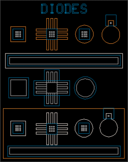
Determine the reverse breakdown and turn-on voltages for the round, square, and
finger diffusion #1 and #2 diodes. From top to bottom in the above figure are the
diffusion #1 diodes, diffusion #2 diodes, and Schotty barrier devices. The Schottky
barriers will not be used in this section. Remember to record the method used to
determine reverse breakdown voltage (line fit and extrapolation, or current of -1
mA, etc.)
Questions
- Which diode had the smallest absolute reverse breakdown voltage? Why? Is it the
one you expected?
Optical Effects
Theory
There are two round diffusion #1 and diffusion #2 diodes. They are approximately
the same size, but one diode is not covered by the aluminum contact. Optical injection
will affect the reverse leakage current.
As photons hit the silicon, they will create electron-hole pairs which will drift
in the field to produce current. The intensity of light
should be proportional to
the number of electron-hole pairs created and the current.
Measurement
Measure the reverse leakage current for the exposed diode with the light on, then
with the light off. Be sure to close the cover for the dark measurement.
Make sure that you use the same voltage reference for each reverse leakage current
measurement.
Note whether the light affects the sharpness of the reverse breakdown. You may make
measurements at different light intensity settings, and note the dependence of reverse
leakage current on the light intensity.
Questions
- Does the light affect the reverse leakage current of the diode?
- Do the positions on the light power supply appear to be linear, logarithmic, or
neither? (Use your leakage currents to answer.)
For Additional Information Consult:
- Arthur B. Glaser and Gerald E. Subak-Sharpe, Integrated Circuit Engineering, (Addison-Wesley,
Reading, MA, 1979), pp. 24-26.
- Ben G. Streetman, Solid State Electronic Devices, (Prentice-Hall, Englewood Cliffs,
NJ, 1980), pp. 162-166.
- S. M. Sze and G. Gibbons, "Effect of Junction Curvature on Breakdown Voltages in
Semiconductors," Solid State Electronics, 9, p. 831, (1966)
|
|
Devices
LASI was used for mask layout.
The mask set is currently under revision 1998: Dane Sievers, which is a minor redesign
of revision 1994: Ron Stack. All revisions are based on the work of revision 1991: Kevin Tsurutome.
Answers provided by this service may not be relevant to the materials presented in this website.
|