|
Load Inverters
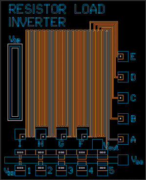
Resistor Load Inverter

The resistor load inverter is designed to be configured several ways. There are five drive FETs, with W/L ratios corresponding to 1, 2, 3, 4, and 5. The FETs designed
length is 20 μm, and the designed widths are 20, 40, 60, 80, and 100 μm. The resistor
has nine pads on it, each corresponding to a different load resistor length.
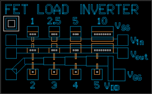
FET Load Inverter

The FET load inverter
has been designed with 4 drivers and 4 loads. You can choose
which driver/load combination to use to produce the best voltage transfer characteristics.
The four drivers are gate 20 μm long, and 20, 50, 100, and 200 μm wide. The loads
are all 10 μm wide and 20, 30, 40 and 50 microns long. The W/L ratios for the drivers
and L/W ratios for the loads are printed on the mask.
|
|
Devices
LASI was used for mask layout.
The mask set is currently under revision 1998: Dane Sievers, which is a minor redesign
of revision 1994: Ron Stack. All revisions are based on the work of revision 1991: Kevin Tsurutome.
Answers provided by this service may not be relevant to the materials presented in this website.
|